Home Articles Developing Software Defined Radio applications with OpenCPI

Developing Software Defined Radio applications with OpenCPI

A visual representation of: Developing Software Defined Radio applications with OpenCPI

Developing Software Defined Radio applications with OpenCPI

Wireless technologies are always evolving and becoming more complex to meet the ever-increasing capacity, reliability and security demands of customers.

The most prominent example of this is the ongoing rollout of the 5G mobile phone network. Over time, the 5G standard will improve and gain new features. With the cost of deploying such a network nationwide in the billions of pounds, the ability for a network operator to modify the functionality of their base stations with a software update is very attractive. This can be achieved using Software Defined Radios (SDRs).

Software Defined Radios (SDRs) have two main components:

  1. Digital Processing: the “software defined” aspect of an SDR. This can be achieved with a range of devices from processors (such as those found in the device you’re reading this on!) through to specialised devices such as Field Programmable Gate Arrays (FPGAs). The functionality of these devices can be modified with software to perform signal processing and control.
  2. Radio-Frequency (RF) Transceiver (transmitter and receiver): the “radio” aspect of an SDR. These convert RF signals received through an antenna into digital signals and vice versa.

Sounds straightforward, right? However, when it comes to developing an application to run on an SDR, things get more complicated. Let’s consider the Analog Devices ADRV9361-Z7035 [1].
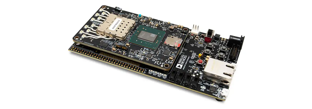
Xilinx Zynq System-On-Module

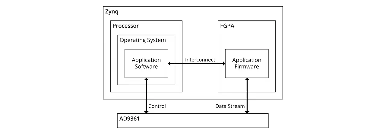
This sports a Xilinx Zynq System-On-Module (SOM) which consists of a dual-core ARM Cortex A9 processor and an FPGA connected internally. The RF Transceiver is an Analog Devices AD9361. To develop an application to run on this SDR, a designer would need:

  • An operating system to run on the processor: this manages running software and handles core system functionality such as access to file systems and networking
  • To develop software in C/C++/Python to add the application functionality on the processor
  • To develop firmware in VHDL/Verilog to implement functionality on the FPGA
  • To develop software and firmware to enable communications between the processor and FPGA and then onto the AD9361
Developing Software - Zynq 1280x450

Xilinx provides a number of different tools (Petalinux, Vitis, Vivado) to do all of this but, whilst the steps sound simple, each can take a developer weeks of effort!

The Open-Source Component Portability Infrastructure (OpenCPI) framework aims to speed up the development process. OpenCPI provides:

  • Component-level development using a set of well-defined interfaces which allows component re-use across multiple platforms.
  • Simplified build system where a developer uses a small set of commands and OpenCPI then calls on vendor-specific toolchains as required to build components for a target platform.
  • Run-time application control to manage the lifecycle of a running application and provide simplified control.

These aspects can allow a developer to create and run an OpenCPI application without having to write any of their own code (providing suitable components and platform support already exist!).

A Simple Example

The best way to explain the benefits of OpenCPI is with an example. For this, we will create a simple application that reads a set of values from a file, multiplies each value by a constant, then writes the result to another file. We will then run our application on the ADRV9361 SDR described earlier.

A caveat before starting: this example assumes that the developer has already installed OpenCPI and the tools required by their platform vendor of choice. For this example, we use Xilinx Vivado and Vitis. The installation of OpenCPI is covered in its documentation [2].

To develop an application using OpenCPI, we start by breaking down our application into components and define how they are connected. Each component is responsible for a well-defined bit of data processing. In our example, we will use:

  1. File Reader: this reads data from a file on disk and outputs it to the next component
  2. Constant Multiplier: this multiplies the data by a constant and outputs it to the next component.
  3. File Writer: this writes the data it receives to a file on disk.

file reader-constant multiplier-file writer

At this stage of development, the developer does not need to consider where or how the components will be implemented (processor vs. FPGA). Components use the same interfaces regardless of where they are implemented. These interfaces consist of:

  • Ports: used to transmit streams of messages. The format and contents of each message is defined by a Protocol Specification and one port can carry a number of different message types defined by opcodes.
  • Properties: used for control and monitoring of components. In our example, the constant used for multiplication could be a property.

With the components identified, a developer can then explore existing OpenCPI component libraries to find if they have already been implemented (reducing your own development time!). The File Reader and File Writer components already exist within the OpenCPI Core project [3]. This means we only need to implement our Constant Multiplier component.

To begin development of our application, we create a project to work in with:
ocpidev create project plextek

Within our new project folder we can create a components library with:
ocpidev create library components

We can then create a template specification file for our constant multiplier component with:
ocpidev create spec constant_mutliplier_s_l

Specification files are defined in XML documents in OpenCPI. For our component we have the specification below which has:

  • Input port which accepts streams of short (16-bit signed) values
  • Short (16-bit signed) multiplier value
  • Output port which generates streams of long (32-bit signed) values
<ComponentSpec>
  <!-- Input port -->
  <Port Name="input" Producer="false" Protocol="short_timed_sample-prot"/>

  <!-- Constant multiplier -->
  <Property Name="multiplier" Type="short" Writable="true"/>

  <!-- Output port = input * multiplier -->
  <Port Name="output" Producer="true" Protocol="long_timed_sample-prot"/>
</ComponentSpec>

With the component interfaces specified, an implementation of the component, or worker, can be created. This is the point where a developer should consider if they want to implement their component on the processor or FPGA. In this example we will demonstrate both methods starting with a processor-based or Resource-Constrained C (RCC) implementation:

ocpidev create worker constant_multiplier_s_l.rcc

OpenCPI generates the bare essential code to build the worker as well as a run() method. The run() method is called when data is available on the input and the output can accept new data. We implement our functionality as follows:

RCCResult run(bool) {
    // Get number of input samples and resize output buffer to match
    size_t number_input_samples = input.sample().data().size();
    output.sample().data().resize(number_input_samples);

    // Get pointers to input and output buffers
    const int16_t *input_buffer = input.sample().data().data();
    int32_t *output_buffer = output.sample().data().data();

    // Multiply each input by the multiplier
    for (uint i=0; i<number_input_samples; i++) {
      output_buffer[i] = input_buffer[i] * properties().multiplier;
    }
    
    // Tell OpenCPI that all ports should be "advanced"
    return RCC_ADVANCE;
  }

One question that arises from this example is why do we have to use input.sample().data().data() to access the data on the port? The answer comes from the protocol specification mentioned earlier. Our input protocol is defined in the OpenCPI Core project [3] and the section of interest is:

In this protocol we have an operation called sample with an argument of data. This then breaks down as:
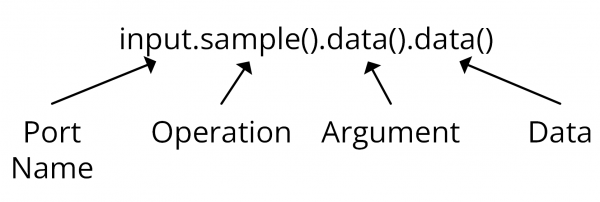
diagram

With our component written, we can build it with:

ocpidev build --rcc-platform xilinx19_2_aarch32

The xilinx19_2_aarch32 platform uses the C++ compilers provided by Xilinx Vitis to build for the ARM processor of the Zynq.
At this point, we have our worker ready to run on the processor. The next step is to create an OpenCPI application which tells OpenCPI what components are needed and how they are connected. A blank application can be created with:

ocpidev create application constant_multiplier

Applications are defined in XML documents (much like everything else in OpenCPI!) and our example application is shown below:

<Application>
  <!-- File Reader -->
  <Instance Component='ocpi.core.file_read' Connect="constant_multiplier_s_l">
    <Property Name="fileName" Value="input.bin"/>
  </Instance>

  <!-- Constant Multiplier -->
  <Instance Component='local.plextek.constant_multiplier_s_l' Connect="file_write">
    <Property Name="multiplier" Value="10"/>
  </Instance>

  <!-- File Writer -->
  <Instance Component='ocpi.core.file_write'>
    <Property Name="fileName" Value="output.bin"/>
  </Instance>
</Application>

We can then deploy our application to our ADRV9361 by copying the built files across along with the operating system image OpenCPI generates during installation of the platform.
Before we run the application, we have to generate a binary input file with numbers in. We can do this by running:

echo -n -e ‘\x01\x00\x02\x00’ > input.bin

This puts the 16-bit numbers 1 and 2 in the input file (in little endian). We then run:

ocpirun constant_multiplier.xml

At runtime, OpenCPI searches all available component libraries for workers that meet the needs of the application and connects them together – a bit like assembling a jigsaw. After running the application we see an output.bin file appear and examining the file with the hd command we see contents:

0a 00 00 00 14 00 00 00

This is 10 and 20 in hexadecimal format (again in little endian). The output is longer (twice as long in fact) than the input as the output is formed from 32-bit numbers whereas the input uses 16-bit numbers.
To demonstrate how simple it is to achieve the same result on an FPGA we can also create a Hardware Description Language (HDL) worker. We create the worker template with:

ocpidev create worker constant_mutliplier_s_l.hdl

We then create our VHDL implementation of the multiplier:

architecture rtl of worker is
begin
  -- Data on ports and in properties is easily accessed
  output_out.data <= std_logic_vector(signed(input_in.data) * props_in.multiplier);

  -- Output ports are "given" to and input ports are "taken" from
  output_out.give <= input_in.ready and output_in.ready and ctl_in.is_operating;
  input_out.take <= input_in.ready and output_in.ready and ctl_in.is_operating;

  -- Ports use qualifiers to give the validity of the data and position in a message
  output_out.valid <= input_in.valid and ctl_in.is_operating;
  output_out.som <= input_in.som;
  output_out.eom <= input_in.eom;
  output_out.eof <= input_in.eof;
end rtl;

The worker can then be built with:

ocpidev build --hdl-platform adrv9361

As OpenCPI cannot generate an FPGA bitstream at runtime, we have to do a bit more preparation before we run our FPGA worker. We must make an assembly where we will place our worker. Assemblies are very similar in structure to an application and consist of the workers the developer wants, the connections between the workers and any connections to be made outside of the FPGA. We create a blank assembly with:

ocpidev create hdl assembly constant_multiplier

Within this assembly we instantiate our component and declare it to have Externals. External ports are accessible outside of the FPGA assembly and by default are connected to the interconnect between the FPGA and processor on the Zynq.

<HdlAssembly>
   <Instance Worker="constant_multiplier_s_l" Externals="true"/>
</HdlAssembly>

At this point, we run:

ocpidev build --hdl-platform adrv9361

As before, we can copy the build files across to our ADRV9361 and, to prevent OpenCPI using the RCC worker, we can delete its object file. We can then delete the output.bin file and once again run:

ocpirun constant_multiplier.xml

OpenCPI now can’t find our RCC worker so instead loads the FPGA bitstream, connects this to the file read and file write (which still run on the processor) and then runs as before. Simple!
The story doesn’t end here, and OpenCPI offers much more beyond what I’ve discussed in this post! Just one example is the interface that it offers to allow real-time management and control of OpenCPI applications and its workers from a separate C++ program.

So what’s the catch?

This post has focussed on a very simple example of using OpenCPI to perform signal processing on a platform which offers multiple options for where to execute software. It has a number of advantages to offer:

  • Encourages component re-use – components can be written and well tested once, reducing wasted development time. Open-source libraries of components already exist online too!
  • Developers can construct complex applications using existing components so knowledge of languages such as C++ and VHDL is not required if a component already exists. OpenCPI handles the assembly of the necessary artifacts from the application and assembly XML files provided by the developer.
  • Open source – if it doesn’t meet your current requirements, it can be updated or modified and has an active (and growing) community supporting it.

However, given the complexity of the problems it is trying to solve, it of course comes with some disadvantages too!:

  • If a platform isn’t already supported then there can be significant effort in adding support. This is lessened if the new platform shares attributes with an existing one (for example, if is based on a Zynq or uses an AD9361) as existing code can be re-used.
  • It is still under active development – this means that things are liable to change but also that bugs exist! A developer must be prepared to become familiar with the framework and may also need to get involved with issue reporting to support resolution of issues!

However, it is worth noting that development of the OpenCPI framework has ramped up in the past two years and is now being used by the Ministry of Defence in partnership with industry to create the latest generation of Electronic Counter Measure equipment [4]. This alone suggests that OpenCPI will be around for some time yet.


Contact Plextek

Contact Us

Got a question?

If you have got a question, or even just an idea, get in touch


Technology Platforms

Plextek's 'white-label' technology platforms allow you to accelerate product development, streamline efficiencies, and access our extensive R&D expertise to suit your project needs.

  • 01 Configurable mmWave Radar Module

    Plextek’s PLX-T60 platform enables rapid development and deployment of custom mmWave radar solutions at scale and pace

    Configurable mmWave Radar Module
  • 02 Configurable IoT Framework

    Plextek’s IoT framework enables rapid development and deployment of custom IoT solutions, particularly those requiring extended operation on battery power

    Configurable IoT Framework
  • 03 Ubiquitous Radar

    Plextek's Ubiquitous Radar will detect returns from many directions simultaneously and accurately, differentiating between drones and birds, and even determining the size and type of drone

    Ubiquitous Radar
Urban Challenges Rapid RF Propagation Modelling
Urban Challenges: Rapid RF Propagation Modelling

Discover the challenges and solutions for accurately modelling RF propagation in urban settings. Explore the innovative neural network model revolutionising urban RF systems.

Plextek's white paper Sensing in Space
mmWave Technology for Space Sensing and Operations

Discover our advanced mmWave radar platform for safer and more efficient space missions.

Enhancing communication and safety in mining: the role of custom RF system design

We explore the role of custom RF system design in communication and safety within the mining industry, ensuring robust data handling and operational efficiency in challenging conditions.

High-Performance mm-Wave Radar System for in-orbit micro-debris detection - capable of detecting fast-moving particles with relative velocities of up to 15.2 km/s at distances over 60 metres away
Continuing to Lead in Radar Development for Pioneering CLEAR Mission

We continue to advance radar technology for the CLEAR mission, reinforcing the partnership with ClearSpace and the UK Space Agency for sustainable space safety and debris removal.

Revolutionising chronic pain management

Fusing mmWave technology and healthcare innovation to devise a ground-breaking, non-invasive pain management solution, demonstrating our commitment to advancing healthtech.

An artistic impression of the CLEAR mission. © ClearSpace
Pioneering Advanced In-Orbit Servicing

Pioneering a ground-breaking collaboration in advanced in-orbit servicing, setting new benchmarks for space debris removal and satellite maintenance.

A visual representation of: SSL The Revolution Will Not Be Supervised
SSL: The Revolution Will Not Be Supervised

Exploring the cutting-edge possibilities of Self-Supervised Learning (SSL) in machine learning architectures, revealing new potential for automatic feature learning without labelled datasets in niche and under-represented domains.

Unlocking the mysteries of imaging radar data processing

Looking deeper into the cutting edge of imaging radar data processing, where innovative techniques and practical applications combine to drive forward solutions.

Evolving silicon choices in the AI age

How do you choose? We explore the complexities and evolution of processing silicon choices in the AI era, from CPUs and GPUs to the rise of TPUs and NPUs for efficient artificial intelligence model implementation.

A visual representation of: Advancing space technology solutions through innovation
Advancing space technology solutions through innovation

At the forefront of space technology innovation, we address complex engineering challenges in the sector, delivering low size, weight, and power solutions tailored for the harsh environment of space.

A visual representation of: A Programmer's Introduction to Processing Imaging Radar Data
A Programmer’s Introduction to Processing Imaging Radar Data

A practical guide for programmers on processing imaging radar data, featuring example Python code and a detailed exploration of a millimetre-wave radar's data processing pipeline.

Folded Antennas; An Important Point of Clarification

Exploring the essential nuances of folded antennas, ensuring precision and clarity in this critical aspect of RF engineering and design.


Related Technical Papers

View All
Sensing in space The untapped potential of radar for space-based sensing. And how to get it right.
Sensing in space

Space holds vast promise. Orbiting satellites have already enabled global communications and allowed us to learn about our planet's climate. This paper will explain radar, how it works, and why it is suited to space applications. It will also discuss considerations for space companies when deploying any sensing technology. There is no one-size-fits-all when it comes to sensing. Our team works with space missions to assess if mmWave radar is right, and where it is, identify optimal configurations, software, and security to deliver against the performance and SWaP-C goals.

an image of our technical paper
mmWave Imaging Radar

Camera systems are in widespread use as sensors that provide information about the surrounding environment. But this can struggle with image interpretation in complex scenarios. In contrast, mmWave radar technology offers a more straightforward view of the geometry and motion of objects, making it valuable for applications like autonomous vehicles, where radar aids in mapping surroundings and detecting obstacles. Radar’s ability to provide direct 3D location data and motion detection through Doppler effects is advantageous, though traditionally expensive and bulky. Advances in SiGe device integration are producing more compact and cost-effective radar solutions. Plextek aims to develop mm-wave radar prototypes that balance cost, size, weight, power, and real-time data processing for diverse applications, including autonomous vehicles, human-computer interfaces, transport systems, and building security.

an image of our technical paper
Low Cost Millimeter Wave Radio frequency Sensors

This paper presents a range of novel low-cost millimeter-wave radio-frequency sensors that have been developed using the latest advances in commercially available electronic chip-sets. The recent emergence of low-cost, single chip silicon germanium transceiver modules combined with license exempt usage bands is creating a new area in which sensors can be developed. Three example systems using this technology are discussed, including: gas spectroscopy at stand off distances, non-invasive dielectric material characterization and high performance micro radar.

an image of our technical paper
Ku-Band Metamaterial Flat-Panel Antenna for Satcom

This technical paper by Dr. Rabbani and his team presents research on metamaterial-based, high-gain, flat-panel antennas for Ku-band satellite communications. The study focuses on leveraging the unique electromagnetic properties of metamaterials to enhance the performance of flat-panel antenna designs, aiming for compact structures with high gain and efficiency. The research outlines the design methodology involving multi-layer metasurfaces and leaky-wave antennas to achieve a compact antenna system with a realised gain greater than +20 dBi and an operational bandwidth of 200 MHz. Simulations results confirm the antenna's high efficiency and performance within the specified Ku-band frequency range. Significant findings include the antenna's potential for application in low-cost satellite communication systems and its capabilities for THz spectrum operations through design modifications. The paper provides a detailed technical roadmap of the design process, supported by diagrams, simulation results, and references to prior work in the field. This paper contributes to the advancement of antenna technology and metamaterial applications in satellite communications, offering valuable insights for researchers and professionals in telecommunications.

an image of our technical paper
The Kootwijk VLF Antenna: A Numerical Model

A comprehensive analysis of the historical Kootwijk VLF (Very Low Frequency, which covers 3-30 kHz) antenna, including the development of a numerical model to gain insight into its operation. The Kootwijk VLF antenna played a significant role in long-range communication during the early 20th century. The paper addresses the challenge of accurately modelling this electrically small antenna due to limited historical technical information and its complex design. The main goal is to understand if the antenna’s radiation efficiency might explain why “results were disappointing” for the Kootwijk to Malabar (Indonesia) communications link. Through simulations and comparisons with historical records, the numerical model reveals that the Kootwijk VLF antenna had a low radiation efficiency – about 8.9% – for such a long-distance link. This work discusses additional loss mechanisms in the antenna system that might not have been considered previously, including increased transmission-line losses as a result of impedance mismatch, wires having a lower effective conductivity than copper and inductor quality factors being lower than expected. The study provides insights into key antenna parameters, such as the radiation pattern, the antenna’s quality factor, half-power bandwidth and effective height, as well as the radiated power level and the power lost through dissipation. This research presents the first documented numerical analysis of the Kootwijk VLF antenna and contributes to a better understanding of its historical performance. While the focus has been at VLF, this work can aid future modelling efforts for electrically small antennas at other frequency bands.

an image of our technical paper
The Radiation Resistance of Folded Antennas

This technical paper highlights the ambiguity in the antenna technical literature regarding the radiation resistance of folded antennas, such as the half-wave folded dipole (or quarter-wave folded monopole), electrically small self-resonant folded antennas and multiple-tuned antennas. The feed-point impedance of a folded antenna is increased over that of a single-element antenna but does this increase equate to an increase in the antenna’s radiation resistance or does the radiation resistance remain effectively the same and the increase in feed-point impedance is due to transformer action? Through theoretical analysis and numerical simulations, this study shows that the radiation resistance of a folded antenna is effectively the same as its single-element counterpart. This technical paper serves as an important point of clarification in the field of folded antennas. It also showcases Plextek's expertise in antenna theory and technologies. Practitioners in the antenna design field will find valuable information in this paper, contributing to a deeper understanding of folded antennas.

an image of our technical paper
Chilton Ionosonde Data & HF NVIS Predictions during Solar Cycle 23

This paper presents a comparison of Chilton ionosonde critical frequency measurements against vertical-incidence HF propagation predictions using ASAPS (Advanced Stand Alone Prediction System) and VOACAP (Voice of America Coverage Analysis Program). This analysis covers the time period from 1996 to 2010 (thereby covering solar cycle 23) and was carried out in the context of UK-centric near-vertical incidence skywave (NVIS) frequency predictions. Measured and predicted monthly median frequencies are compared, as are the upper and lower decile frequencies (10% and 90% respectively). The ASAPS basic MUF predictions generally agree with fxI (in lieu of fxF2) measurements, whereas those for VOACAP appear to be conservative for the Chilton ionosonde, particularly around solar maximum. Below ~4 MHz during winter nights around solar minimum, both ASAPS and VOACAP MUF predictions tend towards foF2, which is contrary to their underlying theory and requires further investigation. While VOACAP has greater errors at solar maximum, those for ASAPS increase at low or negative T-index values. Finally, VOACAP errors might be large when T-SSN exceeds ~15.
an image of our technical paper
Antenna GT Degradation with Inefficient Receive Antenna at HF

This paper presents the antenna G/T degradation incurred when communications systems use very inefficient receive antennas. This work is relevant when considering propagation predictions at HF (2-30 MHz), where it is commonly assumed that antennas are efficient/lossless and external noise dominates over internally generated noise at the receiver. Knowledge of the antenna G/T degradation enables correction of potentially optimistic HF predictions. Simple rules of-thumb are provided to identify scenarios when receive signal-to-noise ratios might be degraded.

an image of our technical paper
60 GHz F-Scan SIW Meanderline Antenna for Radar Applications
This paper describes the design and characterization of a frequency-scanning meanderline antenna for operation at 60 GHz. The design incorporates SIW techniques and slot radiating elements. The amplitude profile across the antenna aperture has been weighted to reduce sidelobe levels, which makes the design attractive for radar applications. Measured performance agrees with simulations, and the achieved beam profile and sidelobe levels are better than previously documented frequency-scanning designs at V and W bands.
an image of our technical paper
Midlatitude 5 MHz HF NVIS Links: Predictions vs. Measurements

Signal power measurements for a UK-based network of three beacon transmitters and five receiving stations operating on 5.290 MHz were taken over a 23 month period between May 2009 and March 2011, when solar flux levels were low. The median signal levels have been compared with monthly median signal level predictions generated using VOACAP (Voice of America Coverage Analysis Program) and ASAPS (Advanced Stand Alone Prediction System) HF prediction software with the emphasis on the near-vertical incidence sky wave (NVIS) links. Low RMS differences between measurements and predictions for September, October, November, and also March were observed. However, during the spring and summer months (April to August), greater RMS differences were observed that were not well predicted by VOACAP and ASAPS and are attributed to sporadic E and, possibly, deviative absorption influences. Similarly,the measurements showed greater attenuation than was predicted for December, January, and February, consistent with the anomalously high absorption associated with the “winter anomaly.” The summer RMS differences were generally lower for VOACAP than for ASAPS. Conversely, those for ASAPS were lower during the winter for the NVIS links considered in this analysis at the recent low point of the solar cycle. It remains to be seen whether or not these trends in predicted and measured signal levels on 5.290 MHz continue to be observed through the complete solar cycle.

an image of our technical paper
Electrically small monopoles: Classical vs. Self-Resonant

This paper shows that the Q-factor and VSWR of a monopole are significantly lowered when made resonant by reactive loading (as is used in practice). Comparison with a self-resonant Koch fractal monopole of equal height gives similar values of VSWR and Q-factor. Thus, the various electrically small monopoles (self-resonant and reactively loaded) offer comparable performance when ideal and lossless. However, in selecting the optimum design, conductor losses and mechanical construction at the frequency of interest must be considered. In essence, a trade-off is necessary to obtain an efficient, electrically small antenna suitable for the application in hand.

an image of our technical paper
Ku-Band Low-Sidelobe Waveguide Array

The design of a 16-element waveguide array employing radiating T-junctions that operates in the Ku band is described. Amplitude weighting results in low elevation sidelobe levels, while impedance matching provides a satisfactory VSWR, that are both achieved over a wide bandwidth (15.7-17.2 GHz). Simulation and measurement results, that agree very well, are presented. The design forms part of a 16 x 40 element waveguide array that achieves high gain and narrow beamwidths for use in an electronic-scanning radar system.